Add shield walls is used with RF designs that will have metal or metalized shields covering the RF circuits for EMI protection. The size and shape of RF circuits can be complex and odd-shaped, making it difficult and time consuming to draw the plane shapes, conductive areas, soldermask clearances, and component keepouts on the surface layers of the board to provide a grounding surface for the shields.
With this tool, the PCB designer can draw simple lines and circles on userlayers to graphically represent the shields. The software then converts the lines and circles into the complex shapes needed for the shields. All the corners are smoothed out with radii added. Where the lines and circles overlap, they are combined into a single contiguous shape. The board edges are automatically included in the shield wall shapes when the shields intersect the board outline.
The designer does not have to spend a lot of time getting the shapes perfectly aligned or trying to add or remove little bits and pieces to make all the lines go together. They just need to be close, and the tool will do all the work of tying everything together.
If adjustments need to be made, all the objects the tool creates can be deleted quickly. The source lines and circles can be moved as required, then the derived shapes re-created in seconds. This fast do-and-re-do process makes it easy to be flexible with component placement and signal routing. There is never a moment where the designer says, “It will take days to redraw the shields on this board.” Instead, it will always be, “Sure, I can adjust the shields in a few minutes.”
Here’s an example image of the source lines and circles :

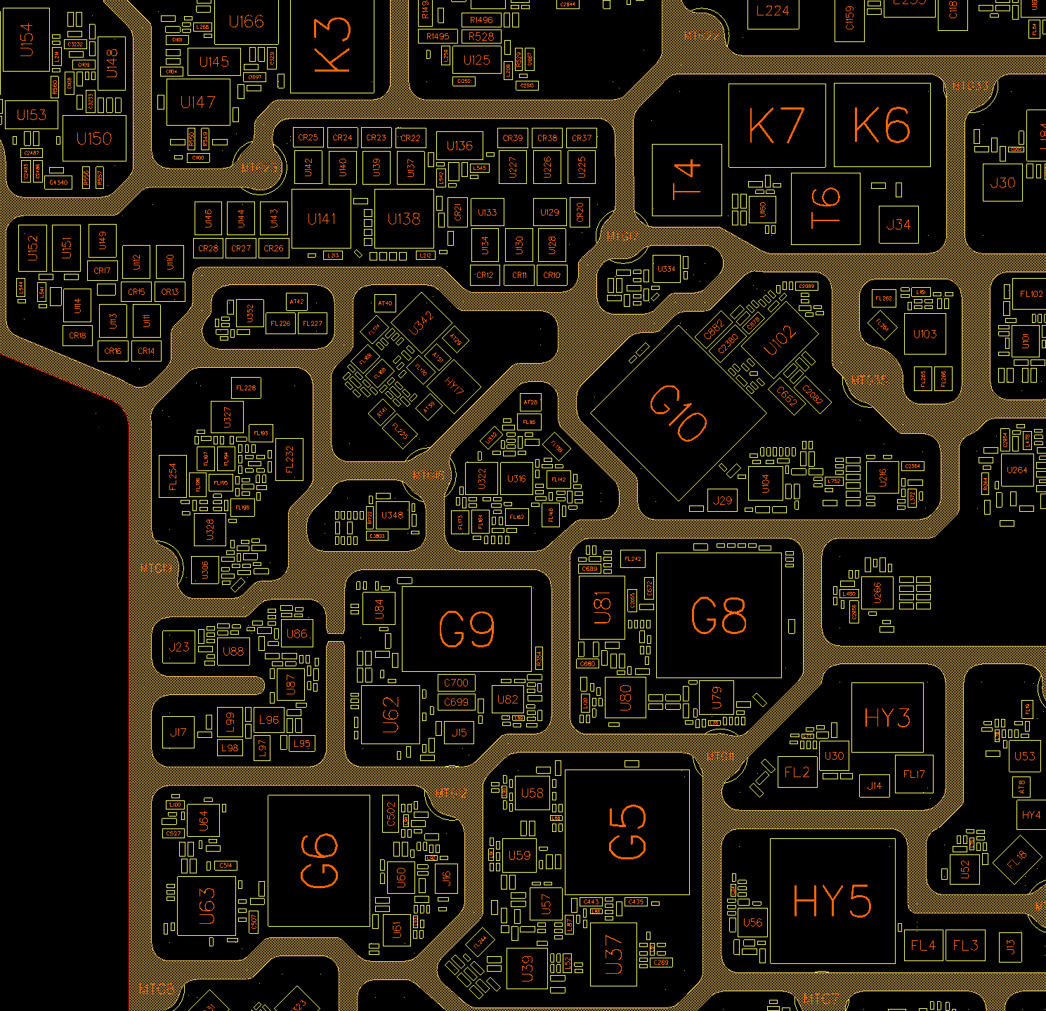
And here is the result after the tool does its work:
Here’s a video showing how it works. Take note – the tool can do shields that go through slots in the board as shown in the video, or shields that sit on the board surfaces, like in the example above.